

Written by
Chris Pearce and Mat LambReading time: 7 minutes
November 10, 2026
Axial Flux Motors & Flexible Power Electronics Reshape Power Generation
Decoupling engine speed from load speed through a controlled DC link delivers compact, efficient, and responsive generator systems for off-highway, marine, and renewable applications.
Demand for compact, fuel-efficient power generation is increasing. Economic pressure, volatile fuel markets, and tighter space constraints are pushing original equipment manufacturers (OEMs) and system integrators to rethink generator design. At the same time, applications are diversifying across sectors. Each sector brings demanding requirements. Some of these verticals are:
- Off-highway and agricultural equipment
- Mobile electrical power generation
- Marine vessels
- Renewable energy systems
In these markets, the conventional generator set (genset) is no longer the only answer. Modern power electronics can operate an electric machine at its most efficient operating points and control every element of a generator system. When paired with axial flux motors, they create a flexible generation platform that matches efficient power conversion to real-world loads.
The result is a shift in how engineers should think about power generation. It is no longer a fixed-speed machine plugged into a fixed-frequency load. It is a controlled system built around a central direct-current (DC) link.
Why Conventional Gensets Leave Efficiency on the Table
A typical commercial-grade genset pairs a diesel engine with an excited-rotor alternating-current (AC) generator. The engine operates at a fixed 1,500 rpm or 1,800 rpm. That speed sets the output at 50 hertz (Hz) or 60 Hz and at regional mains voltage. Any appropriate load can plug in and function.
This architecture is simple, universal, and inexpensive, which is why it dominates the rental market. However, it is designed to be cheap and universal not optimized. The engine does not operate at its most efficient point, and nothing in the system optimizes the load.
Consider a direct, online start induction motor driving a water pump. Starting the motor draws a large current inrush. A soft starter reduces the voltage but does nothing for the frequency. As a result, the genset is often oversized. A 50-kilowatt (kW) pump may need a 70-kW generator. To reduce flow, operators throttle the pump against back pressure. The pump slows, but the engine load barely changes. The system burns fuel at almost full load to do partial work.
Compared with an optimized approach, conventional genset disadvantages include:
- Limited control of output parameters
- A larger footprint from radial flux, separately excited generators
- Slower response to large load changes
- Higher fuel consumption at partial load
Decoupling Engine Speed from Load Speed
The alternative starts with power flow. In motoring, electrical energy from a battery or other source feeds a DC link. An inverter draws from that link and drives the motor, which produces mechanical power. In generating, the flow reverses. The engine drives the machine, and an active rectifier or inverter converts its output into regulated DC on the link. From there, energy flows to the electrical sink, whether that is a battery or other loads.
In an optimized generator, an axial flux motor mounts to the engine and connects to an inverter. This inverter creates and controls a common DC link, for example at 400 volts (V). A second inverter draws from the link and supplies the load with variable frequency and variable voltage, fully decoupled from engine speed.
This separation is the key. The engine can hold its most fuel-efficient speed while the pump operates at its own best efficiency point. Before, standard mains frequency locked the two together.
The load inverter can also shape currents and correct the power factor to keep the whole system efficient. And because power electronics respond much faster than an engine governor, the system can absorb load steps while the engine catches up.
The true benefit depends on the duty cycle. If a system always runs flat out, conventional and optimized designs have a similar total cost of ownership (TCO). Once loads vary, the optimized design pulls ahead. Few applications run at full load all the time, so TCO, not first cost, should drive the architecture choice.
Why Axial Flux Motors Suit Generator Duty
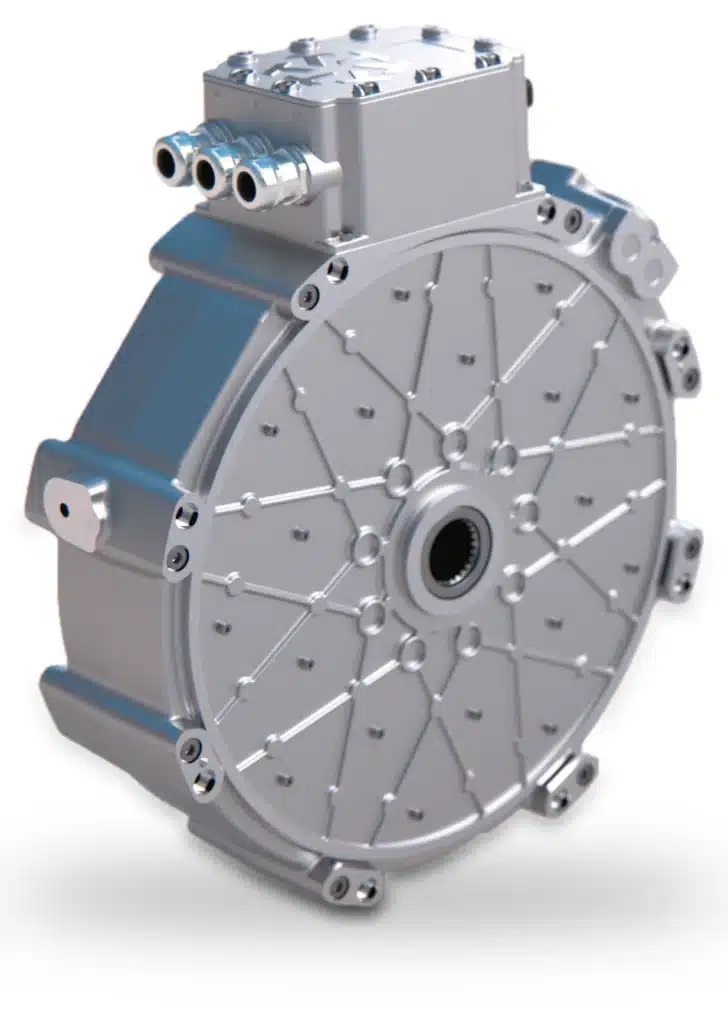
Axial flux motors have a larger diameter and a shorter length than radial flux machines, which earns them the nickname “pancake motors.” The wider rotor carries more magnet material at a larger radius. This raises torque density, lowers core losses, and improves efficiency.
High torque density, measured in newton-meters per kilogram, is especially useful in lower speed applications coupled to diesel engines. The same motors also work with gasoline and other fuels. The short axial length lets the machine fit between an engine and a gearbox, or in other tight spaces, without redesigning the surrounding architecture.
Several integration features make these motors practical for power generation:
- Stackable modules that add power without a new design
- A through shaft that drives auxiliary components mounted behind the generator
- Winding turn counts tailored to a target operating speed
- Flexible orientation of connection boxes and cooling ports
- Compatibility with standard water-ethylene-glycol cooling
Each of these characteristics shortens integration. Matching the engine’s operating speed lets the machine deliver peak efficiency where the system spends most of its time.
Sizing & Controlling the DC Link

The DC link is the staging post of an optimized generator. It lets the engine and the generator each operate at peak efficiency, regardless of what the loads are doing. The generator inverter regulates the link. Output inverters then draw from it to run pumps, traction drives, hydraulic systems, or a grid-tied inverter that produces mains AC.
Sizing begins with several interdependent parameters:
- DC link voltage range, which sets the peak system power and must suit every inverter on the bus
- Generator current, which must deliver the required torque and power
- Peak and continuous loads, so thermal limits never prevent the system from operating as designed
- Total output demand, which must match what the engine and generator can produce
Voltage needs are application specific. A grid-forming inverter needs a DC link above roughly 650 V to produce 415 VAC reliably. Loads that need only 400 V allow for a lower link voltage. The thermal rating of the system is governed by continuous current at the actual coolant temperature.
The link can also be extended. Inverters carry internal capacitance, but added capacitors or supercapacitors let the bus absorb transients larger than the generator’s instantaneous output. A small link with no added capacitance makes voltage control far harder. A battery on the link can buffer surges and provide standby power, so the engine can shut down. DC-DC converters can bring solar or wind energy onto the same bus.
Coordinated control ties it together. The engine holds its most fuel-efficient speed, a slow process. The generator controller adjusts engine load much faster to hold link voltage constant. When loads pull power, the link sags slightly. The generator feeds it, which loads the engine, and the engine governs back to its target speed. A central controller orchestrates these layers across every planned use case.
Architecture Trade-Offs: From Gensets to Back-to-Back Inverters
Inverter-based generation is not meant to displace the rental genset. For a quick, temporary supply, a conventional unit remains cost-effective, even if it is oversized and inefficient. Between that option and a fully optimized system sit other choices.
A synchronous rectifier is a middle path. It uses silicon switches, such as metal-oxide-semiconductor field-effect transistors or insulated-gate bipolar transistors, instead of diodes to create a DC link from a permanent magnet machine. It is more efficient than a diode rectifier, but link voltage is then governed by engine speed. The optimized engine operating point is lost, and DC voltage can sag substantially under load.
Back-to-back inverters provide full control of both the generator and the loads. This allows right-sizing of the engine, generator, inverters, and pumps. The engine can be smaller, fuel use drops, and both the generator and the loads run at their optimal efficiency.
Where loads are dynamic and variable and space and TCO are critical, the back-to-back approach delivers clear benefits. Where a system runs only at full load, the trade-off tilts toward simpler, passive conversion.
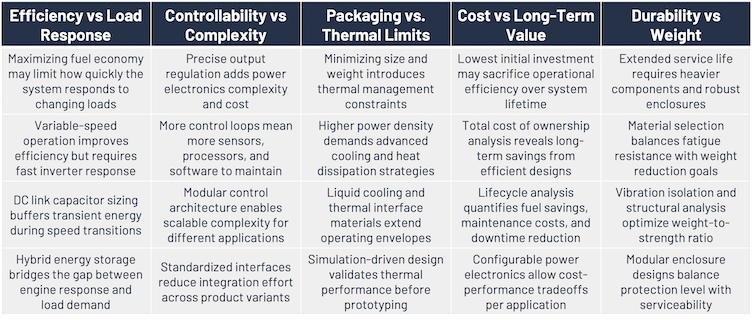
Designing for Diverse Applications & Harsh Environments
Generator architectures vary widely by industry. Off-highway and agricultural vehicles and equipment often share similar approaches. Automotive systems tend toward lower power and less complexity. Marine, rail, and renewable applications each bring their own standards and business requirements. Engineers must account for:
- Inputs, including engines, wind, wave, and tidal turbines, regenerative braking, and flywheels
- Mechanical connections, either direct shaft mounting or pulley drives
- Power buffers, such as batteries, supercapacitors, system capacitance, hydraulic reservoirs, and flywheels
- Control methods, including torque, current, and voltage control, managed in the inverter or by an external electronic control unit
The same principles extend to hybrid systems. In a marine parallel hybrid, for example, an axial flux machine can bolt to the engine bell housing. Its hollow shaft accepts a splined drive shaft to the propeller. The power electronics then act as an electronic clutch, loading or unloading the shaft to charge batteries. A mechanical clutch is needed only for electric-only propulsion, such as quiet operation, where the engine must be disconnected.
Cybersecurity adds complexity. A motor on its own is not subject to cybersecurity regulation. Network-connected power electronics are because an attack could shut the motor down or disrupt service. Rules such as the European Cyber Resilience Act and UN Economic Commission for Europe Regulation 155 make secure inverter design part of the generator specification.
Thermal management is equally critical. Motor output depends on coolant and air temperature. Ratings are often specified at 55°C coolant and 45°C ambient air, so engineers must understand how performance shifts at the extremes. A 50/50 water-ethylene-glycol mix is common. Coolant usually flows through the inverter first, then the motor, so the electronics see the coolest fluid. Parallel cooling is possible, but it needs a manifold and adds complexity.
Shock, vibration, and ingress protection (IP) also matter. Off-highway, marine, rail, and automotive applications each have distinct shock and vibration standards. Ratings such as IP67 and IP6K9K guard against dust, moisture, and high-pressure washdown.
Many generators sit in remote or hard-to-reach locations. They must be compact, reliable, and efficient, and once installed, they must keep working. Pre-validated, plug-and-play systems shorten integration and leave more time for testing.
Why Inverter-Based Generation Is a Gamechanger
Inverter-based generation with axial flux motors is not a universal replacement for conventional gensets. It adds control complexity, and it pays off most if loads vary. Systems that run only at full load gain few benefits.
For dynamic duty cycles, however, the combination changes what a generator can be. Compact, torque-dense machines fit where conventional generators cannot. Flexible power electronics decouple the engine from the load. A controlled DC link becomes a platform for multiple loads, energy storage, and renewable inputs. Together, these allow engineers to:
- Use engines at their most fuel-efficient speed
- Operate each load at its best efficiency point
- Absorb transients without oversizing the engine
- Integrate batteries, supercapacitors, and renewable sources on a common bus
Bidirectional energy flow and grid-tied operation extend the concept further, toward distributed energy platforms that combine generation and storage. For off-highway, marine, renewable, and remote power applications, that flexibility turns power generation from a fixed commodity into an engineered system optimized for decreased TCO.
Subscribe to our newsletter
Power your decisions with expert electrification and hybrid system insights. Subscribe today.
By subscribing you agree with our privacy policy
Featured
Axial Flux Motors & Flexible Power Electronics Reshape Power Generation
Decoupling engine speed from load speed through a controlled DC link delivers compact, efficient, and
Read More
Blog Posts
Market Update: Carmakers Build for Hybrids & BEVs as Supply Limits Come into View
Market Update: Integrated Drive Systems, Buyer Economics & Policy Shape Electrification
Inside EPowerLabs Tech Day 2026
Market Update: Powertrain Options Remain Open & Rail Pairs Batteries with Wires